On the occasion of the presentation of the new “teardown area” Fpt Industrial took the opportunity to take stock of the latest product innovations and the most recent applied technologies. Protagonist among the “Xc13” thermal engines, the first unit that the brand has designed on the basis of new development objectives in terms of efficiency, application flexibility and power supply. Ranging between diesel, natural gas and hydrogen versions. Among the various technologies implemented on the unit, the engine braking system stands out, specific for heavy-duty applications. “High performance engine brake”, the name of the system, designed specifically for “Xc13” based on the technical know-how gained over the years on hydraulically operated cylinder decompression systems. By looking at the power and braking torque curves generated by the engine, it is possible to appreciate the contribution that the system offers in terms of performance. The power remains above 500 kilowatts, close to 700 horsepower, above one thousand 200 rpm with a ramp up that starts at 800 rpm attacking with 225 kilowatts, around 300 horsepower, and continues almost linearly with just under 350 kilowatts, approximately 470 horsepower, reached at a thousand rpm.
The braking torque, on the other hand, sees a linear development which attacks at 800 rpm with just under 500 newton meters and rises to over two thousand and 600 newton meters at a speed of two thousand 200 rpm. This performance is enabled by a distribution system with variable exhaust valve timing created using two rocker arms, a “canonical” exhaust valve and one dedicated to making the unit work in engine braking mode. The two elements alternate during the operation of the unit in activating the exhaust valves and are inserted into the cylinder head via a rocker shaft made in two pieces.
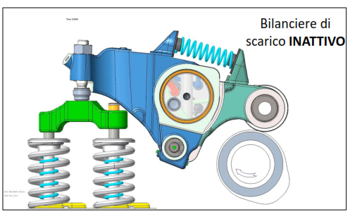
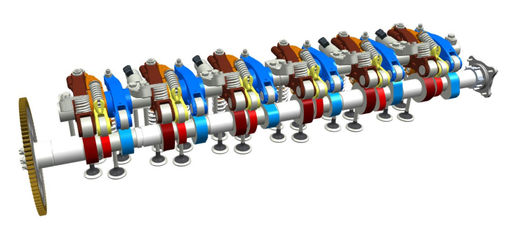
They are controlled by a classic camshaft and each trio of cylinders is therefore associated with a dedicated rocker arm shaft with the first axle shaft which activates the valves of cylinders 1, 2 and 3 and the second those of cylinders 4,5 and 6. Each Three rocker arms are therefore dedicated to the cylinders, two on the exhaust side and one on the intake side, instead of the usual two. The one dedicated to the intake valves has similar characteristics to any other rocker arm used on engines for industrial applications while the one that regulates the exhaust is characterized by an architecture that makes it possible to cancel the movement generated by the camshaft, consequently suspending the functioning whenever necessary. Possibility achieved thanks to a structure that sees the two parts of the rocker arm shaft, a first body on the valve side and a second on the cam side, decoupled from each other unlike when the component is called to work in “normal” conditions. This is thanks to a hydraulic-mechanical system made up of two pistons which normally act as connecting pins between the two sections of the shaft making them integral, but which lose this function when put under pressure by the hydraulic circuit giving rise to a disconnection between the two sections . At that point the cam side section can rotate relative to the valve side section without the associated exhaust valve being actuated. Of note is the presence of a return spring which facilitates the realignment of the two sections. The third rocker is the one dedicated to engine braking. Also in this case it is a disengageable balance wheel and can therefore be managed on-demand based on the required operation. In fact, it sees the presence of an oscillating piston inside the head of the rocker arm which modulates the interaction with the valve tappet. Oscillation can be eliminated through the interaction of a pair of crown gears, one integral with the piston and one with the balance wheel.
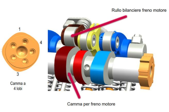
The two crowns are in fact aligned on each other and when the teeth of the second crown integral with the piston are aligned with the slots of the toothed crown integral with the rocker arm, the element can oscillate with respect to the rocker arm, canceling the thrust on the valve tappet. In brake mode, however, the second toothed wheel is rotated so as to allow the alignment of the teeth between the crowns and therefore preventing the relative movement between the piston and the balance wheel. In this case the movement of the rocker arm is transmitted to the valve tappet allowing opening. As regards the engine brake rocker arm, the drive is advanced via a dedicated cam which has a particularity.
It is in fact equipped with four lobes as the exhaust valves must open four times within a cycle in order to ensure the best functioning of the engine braking. The insertion and disconnection of the two rocker arms is advanced hydraulically via solenoid valves, therefore for each semi-shaft of the rocker arm shaft there is a solenoid valve that manages the engine brake rocker arms and one that manages the exhaust rocker arms. The engine control unit is delegated the task of controlling the solenoid valves to manage the flow of oil which activates or deactivates the individual rocker arms. The operation of the entire system is based on two modes called “drive” and “brake”. The “drive” mode identifies engine operation when power is requested, therefore with the accelerator pressed. The “brake” mode instead identifies the condition in which the engine works with the accelerator released. The exhaust rocker arm in “drive” mode behaves like a traditional rocker arm and therefore under the effect of the cam it oscillates around the rocker arm shaft while in “brake” mode the exhaust rocker arm is put out of service. It should be underlined that when the engine brake works, only one of the two exhaust valves is activated, while the second remains closed.
How it works
In all engines, no diesel fuel is injected into the cylinders during the accelerator release phase. Therefore in the cylinders there is only air or in any case a minimum quantity of mixture suitable to prevent the unit from turning off. Therefore, during the compression phase the piston compresses the air which behaves in all respects like a spring. It compresses, accumulating energy in the form of pressure up to the top dead center but once exceeded it returns it to the piston, pushing it downwards. The engine braking system aims to eliminate this air cushion and therefore the “spring” effect. In fact, therefore, when the unit works in engine braking mode, the dedicated rocker opens the exhaust valves at four points in the cycle. The first two correspond to the beginning of the phases which see the upward movement of the piston, the compression and the exhaust phase. At such moments the exhaust valves are opened slightly to draw air from the exhaust manifold which has a higher pressure than the air in the cylinder. And therefore the piston encounters greater resistance during the ascent compared to normal conditions, slowing down. At the end of the piston’s upward stroke there are two “compression release” phases. The exhaust valve is opened again to expel the air cushion. From this perspective, the piston not only does not suffer the rebound induced by the air but must oppose the negative pressure created when the downward movement starts before the intake valves open.


